|
[Newsletters] [Newsletters
TOC] [Newsletters INDEX]
[Cozy MKIV Information]
COZY MKIV ALL EDITION ADDITIONAL PLANS
CHANGES/CORRECTIONS
Updates below include missed items from ALL plans
sets and newsletters -Thanks to Joe
Polenek for compiling this list.
Table Of Contents
- Page 2: Rivets and Page 3: Chapter 16 - Change quantity of
MS20470AD4-10 from 40 to 36. Add: “(8) CCP-42” per Canard
Pusher #49 and #50
- Page 2-2: Nuts - Change MS20364-820 to AN364-820C
- Page 2-3: Chapter 9 Hardware - Change MS20364-820 to
AN364-820
- Page 2-1 and Page 2-3: Foam - Change "(1.5) Sheets
3/4" x 24" x 48" H45 PVC" to "1) Sheet 3/4" x 32" x 48" H45 PVC"

- Page 2-5: Remove horizontal line through the Front
Seat Back layout. Change the description below it to "1
Sheet 3/4" x 32" x 48" H45 PVC"
CHAPTER 9: Main Gear and Landing Brake
- Page 9-6: Fig.30: Change 0.63" to 0.063"
CHAPTER 13: Nose, Nose Gear and Brakes
- Page 13-1: In the prefab parts list, MKNG-3 should be "outside"
and MKNG-4 should be "inside"
- Page 13-14, Fig. 60: Change "17" to "19"
- Page 14-4: Step 10 - After: "When everything is perfect, lay
up a 5 ply BID tape spar to LWY, inside and out, both sides,
as shown on M-8, and a 5 ply BID tape spar to longeron, inside
and out, both sides as shown on M-7."
Add: "All other mating joints get 2-ply BID tape at 45
degrees."
- pulley part number AN210-2A has been superseded by MS24566-2B
- Page 16-1: SCHEDULE A - PREFAB PARTS
For CS-181 Disconnect Insert, change number required from 4 to
2
- Page 16-1: SCHEDULE B - PARTS FROM TUBING
Add: CS-181 STL4130 2 Disconnect Insert - This was a mandatory
change in Canard Pusher #49 and #50
- Page 16-3: Quick Disconnect Drawing - Dimensional error
corrected. Rivets changed from AN470AD4-10 to CCP-42 per
Canard Pusher #49 and #50. In Section II Preface Page 2
'Rivets' and Page3 Chapter 16: Control System, Hardware', See
revised sketch:

- Page 16-7: Figures 4, 6 and 9 - change “18-1-C” to “28-1-C”
- Page 16-7: Figure 9 - Change 1/16" 7x7 cable to 1/16" 7x7 SS
Cable
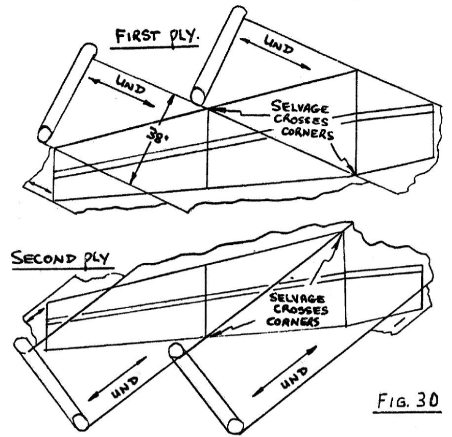
- Page 19-6: Fig.30 Plans show bottom of left wing, but should
show right. See Revised Sketch:
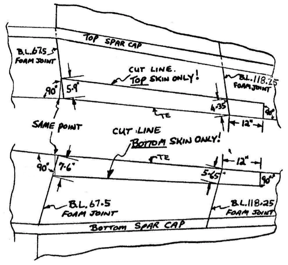
- Page 19-8: Fig.46 Aileron Cut Layout - See revised sketch:
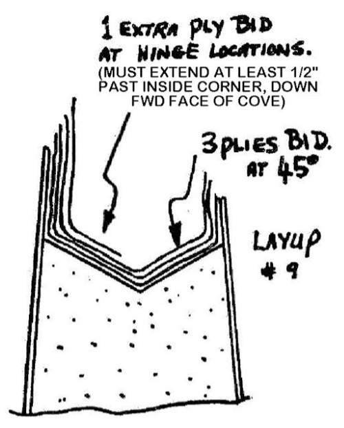
- Page 19-8: Fig.48 Wing Trailing Edge Spar Layup #9 - See
revised sketch:
- Page 19-8: Step 10 - Change “Slice 3/8 in. foam from the
L.E. of the aileron” to “Slice 7/16 in. foam from the L.E. of
the aileron”. This is required to accommodate the increase in
rod diameter
- Page 19-15: View O-O - Delete: “SEE DETAIL A CHAPTER 16 pg
3. THREE PLACES (ROD ENDS and PUSHROD INSERTS).”
Insert: “SEE VIEW G-G CHAPTER 16 pg 4 (ROD ENDS) and CS1A/CS50
CHAPTER 16 pg 3 (PUSHROD INSERTS)”
- Page 19-15: View O-O, CS128 Full Size Pattern - Adjacent to
“.75 D”, add note: “Hole size may vary. Check the outer ring
outside diameter of the specific BC4W10 bearing to be used in
the bellcrank assembly.”
- Page 20-5: Paragraph 4 -
Delete: “The edge at A can be trimmed to allow the rudder to
move farther inboard, or it can be shimmed to hold it farther
outboard.”
Add: “The edge at A can be shimmed to allow the rudder to move
farther outboard. Do not trim it to move the rudder farther
inboard as this could induce flutter.”
[Newsletters] [Newsletters
TOC] [Newsletters INDEX]
[Cozy MKIV Information]
Last Updated Online: November 22nd,
2024 - Added Chapter 2, 9, 13, 15 items
|