Long-EZ N7999H Accident Investigation
Preamble:
I was asked by Tim Sullivan to evaluate the failure of his right
winglet while in flight. This analysis is based on first hand visual inspection
and disassembly of the wing and winglet as well as verbal and written reports
from Tim Sullivan. I have also consulted other Scaled engineers to get their
opinions with respect to the failed structure.
Tim's Flight Description:
"After approaching cruise altitude and cruse airspeed of 165 KTAS the ball
was full left of the bars like this O| | . My left butt cheek was being pressed
into the fuselage. The plane was flying to the right, so a constant left aileron
was needed to keep on course. I tried to use left rudder to straighten out but
that took too much pressure to keep the ball centered. All previous flights did
not have this problem. I saw no other abnormalities during flight. Wingman came
up alongside while at 90 IAS and saw nothing until going back to 135 IAS (5000')
when he said "get that F$&king plane on the ground - the right winglet is coming
off." When on the ground he said he saw the right winglet tip in a slow
oscillation deflecting around 6-12 inches. Still I saw nothing, and felt no
flutter."
During the emergency landing, Tim had a left brake failure, and ran off the
runway. His description of the van impact follows:
"The wing hit the top of the van roof and front windshield intersection at
about the half way point between the end of the strake and the winglet as I hit
the front bumper with the right main gear at about a 20 degree angle from the
van's left to right. I was on two wheels at the time trying to ground loop the
plane due to the left brake being out. So the right wing was high at impact.
During the flight I saw no cracks on the interior of the winglet, therefore the
final blow to the wing was likely due to the upward whiplash from hitting the
van roof."
Neither Tim nor anyone else was injured in the accident.
Failures:
Two failures occurred during this flight and landing:
- Winglet excessive motion in flight, causing a yawing to the right that
evidenced itself as a ball out of center and the need for left aileron to
fly straight, as well as visible deflection
- Left brake failure on landing leading to ground loop and van impact
I will evaluate the first failure in depth, and address the second failure
only to the extent that Noe Ramirez (who is performing the repairs on
Tim's aircraft) has theorized on it.
Narrative:
Whiteman and Aircraft Disassembly:
On December 19th, 2009, a co-worker and I flew down from Mojave
(KMHV) to Whiteman
Airport (KWHP) near
Los Angeles in his Long-EZ to visually inspect Tim's Long-EZ, N7999H and
attempt to determine the root cause of the winglet failure that Tim had
experienced. We taxied to Noe Ramirez's hangar, and with Chris Randall,
the four of us began looking at the aircraft, concentrating on the right wing
although we also looked at the nose, landing gear, and left wing.
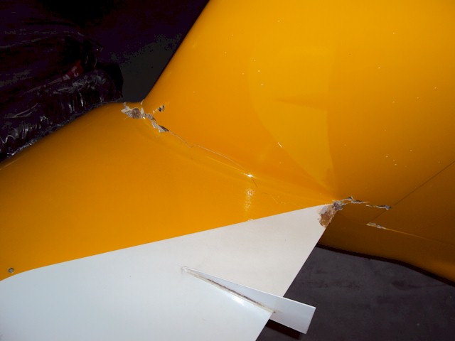
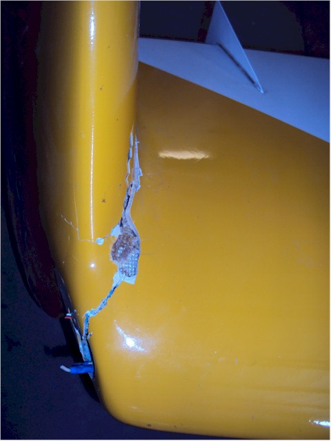
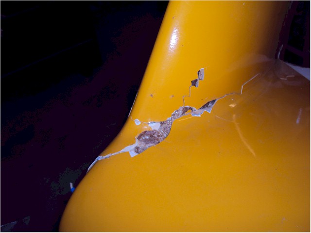
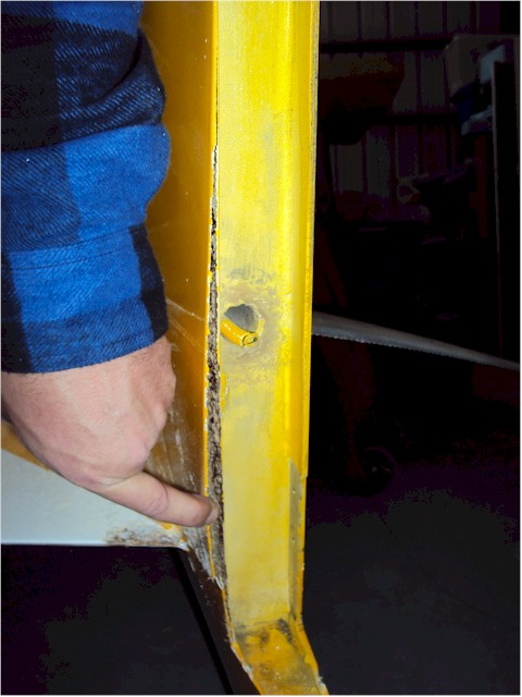
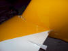
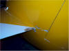
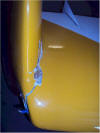
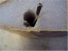
The right wing/winglet joint showed substantial exterior visible damage, as
shown in the following pictures:
 |
 |
 |
 |
 |
| Overall Interior View |
Trailing Edge from Top |
Leading Edge Damage from
Front |
Trailing Edge from Bottom |
Leading Edge Damage from
Side |
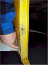
We could easily move the tip of the winglet 6" to 8" outward from it's
normal position with very little force. Pushing inward, however, the winglet
felt stiff. There was clear laminate failure near the leading edge as seen in
image 3, delamination of the trailing edge as seen in image 2, and a crack
running along the micro blend radius (not unexpected) from the leading edge to
the trailing edge.
We discussed possible forensic methodologies and decided that since the
rest of the wing looked OK, except for the van impact damage, and the winglet
looked OK as well, we would concentrate only on the wing to winglet joint
area. Since this is a relatively small section, we decided to cut the joint
out of the wing and bring it back to Mojave for further dissection and
analysis. With a hand saw and Fein tool, we cut off the winglet about 8" up
from the joint and then cut the joint off the wing about 8" inboard from the
joint.
We then flew back up to Mojave (KMHV),
with me holding the wing/winglet joint section on my lap in the rear seat of
my co-workers Long-EZ. My first goal was to expose all the structural
layups of the joint so that we could determine build quality, failure areas
(if any), and see any other pertinent information.
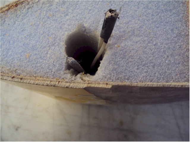
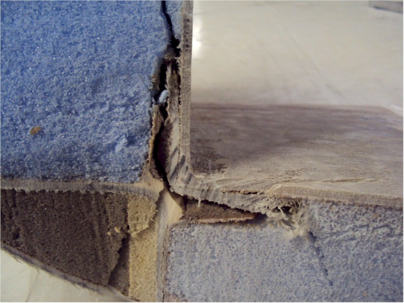
Mojave Fill Removal and Layup Exposure:
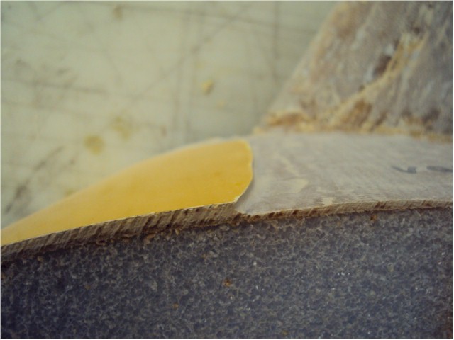
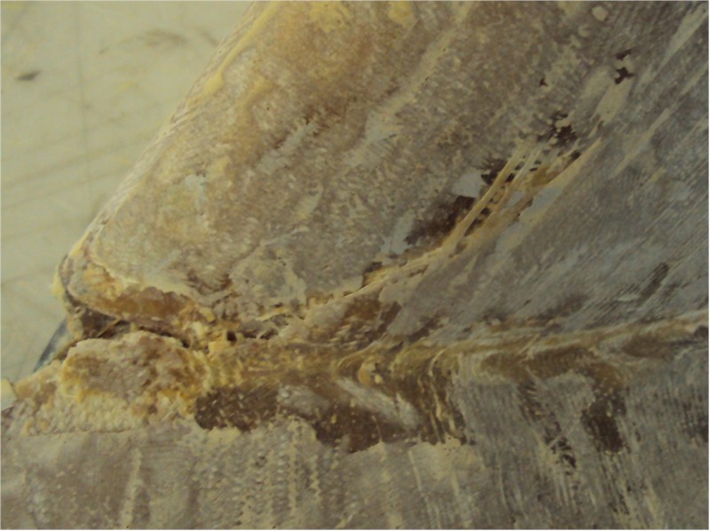
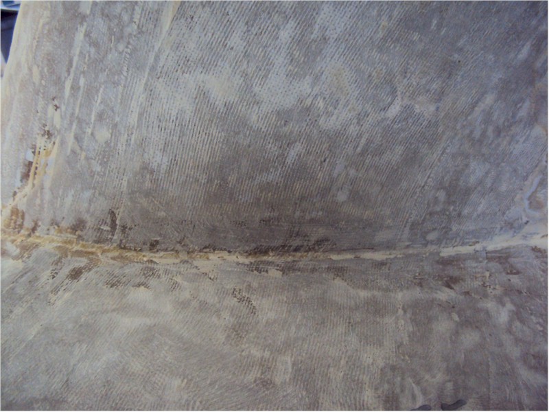
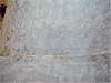
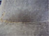
The first thing we noticed upon joint cutting and fill removal was the very
large quantity and thickness of the micro fill over almost all of the wing and
winglet surface. To me, this is indicative of poor shape control during the
hot-wiring and layup process, leading to the need for 1/16" - 1/8" of fill
over essentially 100% of the wing/winglet to bring it into correct contour.
Most of my time with the grinder was spent in removing fill and generating
copious quantities of dust in the dust booth. You can see the representative
fill thickness in these two photos:
 |
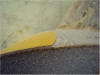 |
| Lower Surface - Wing showing Fill
Thickness |
Upper Surface - Wing showing Fill
Thickness |
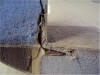
The next thing we noticed upon preliminary inspection, joint cutting and
fill removal was that at least one glass-to-glass bond, at the trailing edge
of the winglet rudder cove, which was not built to specifications - there was
micro between the winglet skin and the rudder cove BID layups, as shown in the
three photos below:
 |
 |
 |
| Delamination of
Glass-to-Glass Bond |
Section through
Delamination |
Inner Winglet Skin Peeled
Back - Micro in GtG Joint |
While there was delamination of the Glass-to-Glass bond at the trailing
edge of the wing near the winglet joint, there was no micro in that joint - it
was a correctly fabricated joint.
After removing the lower winglet, further fill removal revealed the
exterior UNI/BID layup on the bottom of the wing/winglet joint - noted as
Layup #3 in Figure 17 in Chapter 20 of the COZY plans (I believe the
nomenclature is the same on the Long-EZ plans - correct me if I'm wrong), as
well as the wing and winglet lower/outer skins. The #3 layup looked nominal,
with the correct number of plies and approximately the correct dimensions.
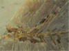
Removing fill on the wing upper and winglet inner skins, as well as the
fillet, revealed the large crack and incipient delamination near the leading
edge of the winglet. While this could be seen in the original viewing prior to
fill removal, the extent of the damage became clearer after the fill was
removed. This seemed to be a consequence of the winglet motion - not a cause.
We could also see that the reinforcing UNI/BID layup #4 had been applied very
poorly, with the UNI fibers not aligned and kept straight as they transited
the joint corner.
 |
 |
 |
| Leading Edge Crack /
Delamination |
Layup #4 - Fibers not
Straight |
Layup #4 - Fibers not
Straight |
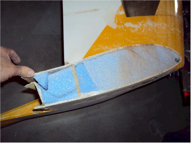
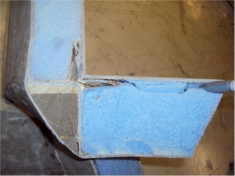
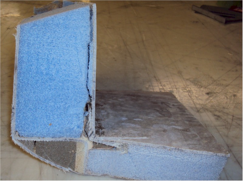
Joint Sectioning and Interior Layup Exposure:
Once the fill was completely removed and the exterior layups examined, I
sectioned the joint vertically through the approximate center of the
reinforcing layups #3 and #4 so that I could see the condition of all the
interior layups in the joint. This revealed a plethora of build errors and
problems with the winglet joint. Photos of the joint section are below:
 |
 |
 |
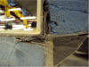 |
| Overall View |
Delamination in Winglet
Skin / Foam Joint |
Close-up of Layup #1 and
Layup #2 Looking Rearward |
Close-up Looking Forward |
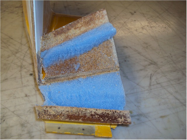
We can see in multiple photos that there is micro between the Layup #1 8
BID and the interior of the wing and winglet skins. Referencing Figure 14 in
Chapter 20 of the plans as well as the text in Step 4, we can see that the
glass interior surfaces of the wing and winglet should have been sanded smooth and the micro
left over from the removed triangles of foam completely removed. This micro in
the Glass-to-Glass joint should not be there.
We can also see that urethane foam was used for the small triangular foam
wedges around Layup #1. While the type of foam to use for these wedges is not
explicitly called out in the plans, since Styrofoam was removed to create the
cavities, Styrofoam should be used to fill the space after Layup #1 is
applied. We can see that there are substantial voids around the urethane foam
wedges - this space must be completely filled with flox and foam.
The space between Layup #1 and Layup #2 clearly has micro not only around
the layup, but between the two layups. The plans clearly state, and show, that
flox should be used in this area and Figure 15 clearly shows that the two
layups should be touching one another. This is a major discrepancy. Major
cracks through this area can be seen, and this is the primary reason for the
winglet motion.
A minor issue, but an issue nonetheless is the fact that Block "A" - the
urethane block in the triangular space that is later covered with Layup #3, is
not sanded flat as shown in Figure 16. While not very rounded, it is not flat
with rounded corners/edges.
One other issue that cannot be seen in the pictures but could be discerned
by close examination of Layup #1 and Layup #2 were that both layups seemed
very dry - the end of layup #2 toward the front of the winglet evidenced very
little epoxy in the fibers.
Complete Forensics:
At this point, the disassembly and sectioning was complete. Three engineer
co-workers examined the sectioned parts of the wing/winglet joint and
concurred on the issues noted, as well as their severity and contribution to
the failure.
Analysis:
Issues:
The construction issues noted in the narrative are summarized as follows, in
order of probable importance:
- Micro, not flox, used in between layup #1 and #2
This is the single
largest problem noted in the wing/winglet joint. Layups #1 and #2 are
supposed to be touching each other at the corner (per the plans figures) and
should be surrounded by flox to ensure shear transfer between the two
layups. As noted in issue #2, the stiffness of the joint will be good under
very low loads (pushing/pulling by hand on the winglet), but the strength
will be miserable in relation to what it should have been.
In this case,
the low strength of the micro, it's inherent brittleness, and it's low shear
strength capability are what led to the joint failing and the delaminations
of the wing/winglet trailing edges, the delaminations of the wing/winglet
foam to skin joint and the crack/delamination of the winglet leading edge
and reinforcing layups.
- Micro in glass-to-glass bond of layup #1 to interior wing/winglet
skins
When the wing and winglet are originally fabricated, the skin is applied over the foam with
micro fill. When the foam wedges are later cut out, any areas where there will be a glass-to-glass bond are supposed to be
sanded smooth - not just having the foam removed, but also removing all
adhered micro so that the glass-to-glass bond will truly be glass-to-glass,
not glass-to-micro-to-glass.
Although the stiffness of the structure will
be approximately correct even with the micro between the glass layers, the
strength will be substantially compromised. Once the glass to micro bond
breaks, there will be no stiffness whatsoever.
It is not acceptable to have micro between glass layers.
- Micro in glass-to-glass bond in the winglet rudder cove
When the
winglet is originally fabricated, the skin is applied over the foam with
micro fill. When the rudder is later cut out and the cover fabricated with
BID, any areas where there will be a glass-to-glass bond are supposed to be
sanded smooth - not just having the foam removed, but also removing all
adhered micro so that the glass-to-glass bond will truly be glass-to-glass,
not glass-to-micro-to-glass.
Although the stiffness of the structure will
be approximately correct even with the micro between the glass layers, the
strength will be substantially compromised. Once the glass to micro bond
breaks, there will be no stiffness whatsoever.
Using the same logic as in
issue #2, this is a major issue. It is not acceptable to have micro between
glass layers.
- Not enough flox for layup #1 and foam wedges - large voids
The flox in
this area is used as a backup material to help prevent buckling of the skins
and also to ensure that when the foam wedges are inserted, there is adequate
pressure to keep the glass layup touching the skin interior surfaces. Large
air voids in a layup are never OK.
- Poor fiber straightness in reinforcing layup #4
The UNI fibers in this
layup are there to provide both strength and stiffness for the wing/winglet
joint. If the fibers are not oriented correctly (and in this case, oriented
along the wing span and winglet span, without wiggles) then both the
strength and stiffness of the joint will be compromised. Although in this
case, this joint did not fail, this issue is indicative once again of the
general lack of build quality.
- Block "A" not flat as shown in Figure 16
Again, not a
contributor to this particular failure, but an indication of not following
the plans closely and understanding the intent of the instructions.
- Dry fibers/layups for Layup #1 and Layup #2
Again, not a contributor
to this particular failure, but an indication of not following the plans
closely and understanding the intent of the instructions.
- Substantial Excess micro fill, denoting poor fabrication contouring
In
and of itself, this is meaningless in the context of winglet structural
failure - however, in my mind, if the construction quality was such that
1/16" - 1/8" of fill was required over essentially the whole wing/winglet
structure, that does not bode well for the rest of the construction quality
and the ability to follow the plans direction. Given the rest of the
fabrication quality issues, I think that this correlation is clear.
- Void at corners of wing shear web/spar (not mentioned in narrative, but
noted when cutting joint off of wing)
Again, not a contributor to this particular failure, but an indication of
not following the plans closely and understanding the intent of the
instructions.
Aircraft History:
The aircraft in question, N7999H, was purchased as a partially built
project (canard and elevators in primer, wings complete with winglets installed
- rudders and ailerons cutout, partially built fuselage and other parts to
finish) and completed by Tom Howard of Burbank, CA in 1987. The high performance
rudder modification was implemented after the original rudders were fabricated,
but still during the build and prior to first flight. All structure was
completed prior to first flight, and no major modifications were performed on
the wing/winglet in the intervening 22 years except for a whole aircraft repaint
in 2001 by Tim Sullivan.
Tom Howard owned and flew the aircraft from it's completion in 1987
until selling it to Tim Sullivan in 1999 - a 12 year span of safe flying,
with a total of 1400 hours.
Tim flew the aircraft safely, with no indication of winglet problems or motion
for another 10 years prior to this accident.
For some reason, during this flight, the winglet joint deteriorated to the
point where motion could occur. The winglet experienced an outward force and
oscillated back and forth, also causing the aircraft to yaw to the right.
Summary:
Causes of Winglet Failure:
Aerodynamics:
The aerodynamics of the winglet are subtle. In theory, the winglet ALWAYS
creates an inward force, due to it's mounting incidence angle, vortex
position, and rudder deflection angle capability. However, real aerodynamics are
rarely identical to theoretical aerodynamics, and unsteady flows can exist. In
this case, whether a structural failure led to a deflection of the winglet at
high IAS's which then caused an outward force, or whether an outward force
caused the structural failure in a weakened wing/winglet joint is unknown. What
is known is that an outward force of an oscillatory nature (at low frequency)
occurred and set up a oscillating motion of the winglet, which stopped upon
slowing down and reducing the forces on the winglet.
Structure:
In my opinion, and that of the other engineers who examined the parts, the
structure that failed first which substantially decreased the stiffness of the
joint and which then allowed the rest of the structure to begin failing was the
Layup #1 to Layup #2 joint, not touching and surrounded by micro rather than
flox. As the winglet began moving, the weak bond at the rear of the rudder cove
unzipped, and the further motion of the winglet began cracking and delaminating
the leading edge area and reinforcing layups on the wing top / winglet medial
surface.
Root Cause:
Originally, I wrote:
This is unknown. Tim states that at no time since he owned the
aircraft did a large, outward impact force occur on the winglet which might have
caused a failure of the interior joint. Since Tim did not notice any
problems with the winglet until this last flight, his claim seems reasonable.
This leaves the possibility of slow (over a 22 year period) fatigue cracking of
the interior joint, which just happened to fail catastrophically on this flight.
22 years of flight - over 1000 hours - could easily put millions of stress
cycles on the weakened joint. At some point, the crack will grow large enough to
propagate quickly through the rest of the joint, and then the above structural
failure sequence occurred.
January 25th, 2010 Update:
Apparently just prior to N7999H's last flight, Tim had been parked at
a fly-in in northern CA. A major dust devil came through and witnesses claim
that it passed directly over Tim's aircraft. I postulated that the winds
from the dust devil had thrown something against the winglet and then carried it
away so that no direct evidence of impact would have been left.
Tim responded:
No evidence was found on the winglet of an impact and no one recalls any
debris around the area but it could still be possible. I want to emphasis that
the dust devil I was told about was not one that you see in your court yard
with a few leaves swirling round. It was apparently 40 feet or so across and
spun two chocked Stearman around along its path and went right over my plane
diagonally from back to front.
So lets assume that there was no impact of an object. I don't know much about
dust devils, but this page:
http://www.futurecam.com/dustDevils.html
indicates that the core airspeed might be up to 70 mph. A corroborating web
page:
http://en.wikipedia.org/wiki/Dust_devil
also indicates wind speeds that could be in that neighborhood.
Now, the winglets were designed to take a max CL sideslip
at cruise speed (let's say 150 mph for an original O-235 Long-EZ), so 70 mph
would be about 1/4 the force that it was designed for. Given the replacement of
flox with micro in the winglet joint in question, the strength of which in
tension is far less than
1/4 that of flox, maybe the air loads of the dust devil alone were enough to
fracture the micro joint and cause the subsequent winglet motion.
I assume that, not being based in Mojave, Tim's plane had never
experienced a 70 mph crosswind before, and that this dust devil could very
easily have been the highest outward side load that the winglet had ever seen.
This, to me, is the best explanation for the timing of the winglet
failure. If so, it's good to have a reasonable explanation for a root cause -
high cycle fatigue, while possible, was not a very emotionally satisfactory
answer. Now, what should be clear is that a properly built winglet would NOT
have been overly stressed and would not have failed in this situation. Heck -
only one of two incorrectly built winglets failed (assuming the other winglet
was built in the same manner as the first one).
Knowing that an extraordinary atmospheric condition might have been the root
cause of the failure doesn't change the fact that poor construction technique
was a time bomb that severely compromised the structure, laying in wait for 22
years for a large stressor to come along.
Causes of Brake Failure:
Noe Ramirez at Whiteman Field is repairing the aircraft. While we were there,
he pointed out where the left rudder cable, which actuates the brake cylinder on
the firewall, had a nicopress sleeve attached to it in the rear seat region on
the pilot side of the cockpit. In the operating range of the cable, there is a
small lip in the structure, which the nicopress sleeve could catch on. If
caught, the motion of the cable would be restricted and the left brake could not
be applied.
Noe's assumption, and one with which I concur, is that in the excitement of
landing in a very stressful situation, Tim applied the brakes hard and of
course, the law of averages being stacked against us, the nicopress sleeve
caught on the lip in this particular situation. Since Tim was stressed
and trying to stop quickly, he did not release and re-apply the brakes - he
merely pressed harder which did nothing except make the aircraft swerve to the
right even harder as the right brake worked and the left did not.
As a mea-culpa, at least 10 Condition Inspections of this aircraft were done
by A&P's that were not the person holding the Repairman's Certificate during the
10 years that Tim owned the aircraft. I was one of them, doing the
inspection in early 2008, and I did not notice the possibility of the nicopress
sleeve catching on a lip in the rear cockpit. Apparently neither did the other
A&P's who did the other inspections, nor did Tim, who assisted with all
of them.
This failure led to the largest part of the damage to the aircraft, which
involved ripping the landing gear mounting out of the plane, damage to the nose,
and crumpling of the right wing. It should be a lesson in ensuring that the
flight controls are working free and correctly in ALL possible G-loading,
positioning and vibration situations - not just at one G and level.
Conclusions:
Tim sustained a major structural failure of a critical flight
component while in flight. He was able to land safely without any injuries to
himself or anyone else and by that measure the outcome was very, very good.
Since the aircraft had flown safely for 22 years, it's clear that the
aerodynamics of the airplane were nominal and per plans. The same cannot be said
for the structure, however. We have noted numerous anomalies in the build which
indicated poor build quality, at least in the wing/winglet and joint. At least
one of these quality issues having to do with material substitutions and poor
layup technique seems to have been the basic cause of the eventual joint failure
and winglet motion.
Implications:
- So what was the actual danger here? Tim seemed to be able to fly
the plane safely up to 165 kts, even in a major slip and with the winglet
oscillating with a very large amplitude. Was there danger of the winglet
coming off, with a subsequent almost certain loss of control and crash? The
consensus among the engineers examining the structure was that it didn't
LOOK like there was imminent danger of the reinforcing layups on the top
and bottom surfaces delaminating completely, and the winglet coming off. But
that's hardly a ringing endorsement for continued flight. Most probably, the
winglet would have stayed attached for a long period of time, but it's fairly
obvious to anyone who takes a millisecond to think about the situation that
Tim did the right thing by getting on the ground as soon as he possibly
could.
- What are the implications for the LEFT winglet? While it seems to
be acceptably stiff and strong using the "let's push on it and see what it
feels like" test, we have to assume that the internal structure was fabricated
with the same techniques as the right winglet to wing joint, and this is not
acceptable. Noe has already stated that he believes that he will be removing
the winglet from the wing and re-attaching it using the correct structural
procedures. I believe this is the right course of action, given what was found
in the left winglet attachment structure.
I don't know what to assume about
the rest of the aircraft's structure - I think that Noe and Tim
should evaluate whether any OTHER
portions of the structure need to be rebuilt.
- What are the implications for other modifications that people have
contemplated for canard aircraft, such as Blended Winglets, Symmetric
Winglets, or Winglet incidence changes, all with an eye to reducing drag and
increasing speed?
- Blended Winglets - A small but growing number of people either
have or are in the process of implementing blended winglets on E-racers,
Long-EZ's, and COZY's. I have assisted with a couple of these, notably Jack
Morrison's now defunct E-Racer and Chris Esselstyn's COZY, which are the
only two canard aircraft with large radius blended winglets that have flown
that I know about. In both cases, the structural design was such that the
full strength of the wing was carried into the winglet, making no
assumptions about the aerodynamic forces only being extant in the inward
direction, as the plans design does.
What this failure does indicate clearly is the extreme importance of the
internal structure of the wing/winglet joint in maintaining both structural
and aerodynamic integrity of the aircraft. The aerodynamics and the
structure are intimately tied together, and one cannot be changed without
affecting the other. A blended winglet has a substantially different
internal shape and structure than the plans form of the joint, and
modification of this structure to permit a blended winglet should not be
attempted without a deep understanding of all the forces and aerodynamics of
the aircraft.
As discussed on the canard-aviators list and at least one web forum,
there is at least one person fabricating blended winglets on a COZY MKIV
that has not, at least to the extent that he's made public, performed the
necessary engineering, design, or analysis of the structure and has left out
any internal joint structure. Since this will not be obvious to anyone after
the structure is complete, I recommend that no-one fly in this plane unless
or until a full static load test of the wing/winglet joint to proof load
level has been performed.
- Symmetric Winglets - The thought of using symmetric winglets,
rather than the standard Eppler 1230-modified airfoil, for drag reduction
reasons has been suggested, and Chris Esselstyn fabricated his winglets with
an Eppler 1230-M at the root and a symmetric NACA airfoil at the tip. This
will reduce the inward force of the winglet, at least in theory, and at
least in theory reduce the induced drag.
However, as we can see, unless the structure of the winglet is modified
to account for both inward and outward forces with a symmetric winglet, the
plans structure will be wholly inadequate to deal with the aerodynamic
differences, whether or not there is an induced drag decrease. The ability
of the winglet to produce outward force substantially changes the
requirements for the internal joint structure.
- Winglet Incidence Changes - The same argument as for "symmetric
winglets" applies to the idea of changing the winglet incidence angle to
reduce the force produced and subsequent induced drag.
Reader Feedback / Input:
If anyone has any corrections, comments, questions or information that might
help understand this failure in more detail, please contact me at the email
address listed below.
Thank you.
Return to: Cozy MKIV Information
Copyright © 2010, All Rights Reserved, Marc
J. Zeitlin
e-mail: marc_zeitlin@alum.mit.edu
Last updated:
January 25, 2010 - Updated
Root Cause Section with Dust Devil Information